The United Nations predicts that the existing built environment of all cities globally will have to double by 2050, which means that there is a need for efficient and fast building methods (United Nations report, 2018). Part of a solution to this challenge consists of finding novel ways of constructing structures that are light and fast while focusing on specific design agendas. The manufacturing of a flat building assembly that can be formed into its final configuration on-site has several benefits. Reducing or eliminating form-work or scaffolding and avoiding the use of complex 3D manufactured parts saves energy and is efficient in terms of material usage. The proposed design methods in this paper focus on the link between geometry and material processes to shorten production cycles and to use materials more efficiently.
The term ‘sustainable form-active structures’ expresses the relationship between concepts in form finding and material corollaries to create lightweight and low carbon construction methods. Structural form finding is defined as: Finding an optimal shape of a form-active structure that is in an approximate state of static equilibrium. The proposed studies in this paper are tested via full-scale projects that are often exhibited to make the general public aware of issues of sustainability. The idea is based on making a 3-dimensional (3D) structure from a 2-dimensional (2D) material without molds or scaffolding, which has inherent energy benefits and structural elegance. When certain geometric principles are tied to advanced fabrication, 2D sheet goods can be transformed into high-performance building systems in 3D. The reduced material waste during manufacturing combined with shipping lightweight and flat-packed assemblies provides a lower carbon alternative to conventional construction methods in regards to embedded energy. ‘Making’ is an integral part of the proposed research method and the work is often related to initiatives with artists and material scientists. In order to complete the design research on a chosen geometric topic, full-scale pavilions are realized as a proof of concept, which is then vetted by the architectural community and advances the architectural discourse.
The general idea of collapsing objects into a flat state is as common in design as it is in architecture and it is useful to consider the fundamental connection between the two disciplines. Design in its most general definition can be thought of as the conception and planning of the artificial by making aesthetic (in the visual sense) objects that propose an alternative solution to a problem or object with utility (Newell, A. and Simon, H.A. 2019). This means that designers and architects don’t just solve problems, but offer aesthetic alternatives that retain or improve function. These visual manifestations can communicate conceptual ideas and the aspiration of this work consists in communicating sustainable concepts visually. Design has agency in the public dialog of sustainability since it engages people everywhere every day. The characteristics specific to architecture come into play when objects become large enough that spatial qualities emerge. Material production at this scale has massive impacts on global energy use which needs to improve via design research.
Defining a methodology
Investigating design ideas at an academic level requires a definition of design research and its methodology. Design research can be thought of as a systematic search for knowledge of the configuration, structure, purpose, value, and meaning of man-made things. This definition provides an opportunity to use the scientific method when investigating design problems (Cross, N. 1993). The methodology is based on working with academic references and framing design research projects that can be expanded upon via experimentation and making. The steps include (1) defining or finding a form-finding method, (2) creating an ‘analog’, a scaled-down version for experimentation, which performs in identical ways to full-scale structures, (3) exhausting the topic at the small scale, (4) making full-scale prototypes that test the form-finding process and (5) publishing or exhibiting the work to involve a greater audience. The following case studies comply withthese principles and aspire to demonstrate that this methodology is adequate for architectural design research.
The chosen form-finding topics in this paper include (a) Folding along curves, (b) Ribbon surfaces for bending active structures, and (c) Inflatables with 2D to 3D transformations. In all three cases, the underlying geometric research was conducted at small scales and the academic agenda lies in scaling the principles to an architectural scale. Once a novel contribution has been found, a large-scale version is built to test the geometric principle. The feedback from visitors or involved communities validates specific aspects of the projects but also reveals areas for continued study. The following three sections serve as case studies to elucidate the implementation of the above-mentioned methodology. The three topics have been investigated in architecture seminars or studios or have been completed with research assistants.
(a) FOLDING ALONG CURVES
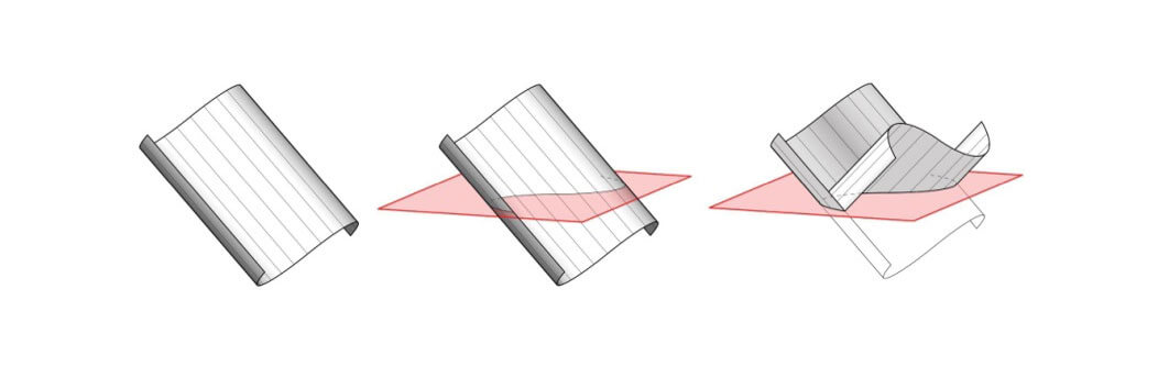
The research question is related to folding along curves and which stability and span one can achieve with this kind of folding at the pavilion scale: Given the geometric constraint of curved folding, which type of shell can be designed and fabricated that uses a single folded surface with compliant hinges? The specific topic in geometry is based on mirror-reflections of any of the three canonical developable surfaces, which are the plane, general cylinder, general cone, and tangent surface. The geometric construction is comprised of cutting the chosen surface with a plane and using a mirror reflection to create a curved crease in the plane (see below).
A general cylinder, intersection with the reflection plane, resulting in a curved fold with mirror-reflected cut off part
The geometry of curved creases
The geometric topic that allows for a 2D to 3D transformation is based on curved folding research. Modeling curved creases in 3D software is difficult as we still don’t know a general mathematical description of the behavior of a curved crease (Demaine, E. et al. 2015).
This design research project relies on a special case, namely: mirror-reflections of a general cylinder. The digital process is controlled in 3D where the cylinder can be mirror-reflected in CAD software. This means that the user is working with the curved surfaces in 3D on the computer. The cylinder is created by extruding a curve and subsequently quasi ‘folded’ with mirror operations. The flattened crease pattern can be used to fold sketch models that behave just like large-scale surfaces would in 3D. The 2D crease pattern includes mountain and valley assignments and in this case, also determines the curve that will touch the ground (seen in bold in the diagram below).
2D to 3D transformation – the left crease pattern automatically creates the shape on the right by curved folding
The design process is based on iterating through many versions and making paper models at every stage. Physical models made of paper serve several purposes such as receiving feedback on surface deformations under stress by pushing down on the model with one’s finger. One main goal consists in finding two appropriate base curves that can serve as guide rails on the ground.
The project
Curved folds have been explored by artists, designers, and geometers since the 16th century and in more recent years origami artists and computational folding experts have further developed the topic. However, there exist very few examples at the scale of a pavilion. This design research project resulted in building a freestanding shell that withstands most forces within the surface. The structure was realized with vulcanized paper, a material that is malleable while moist and becomes stiff after it dries. This enables a building process in two phases: The first phase consists in making a flat assembly; the second – in lifting the assembly with pulleys, folding it into its final configuration, and setting it into a base rail.
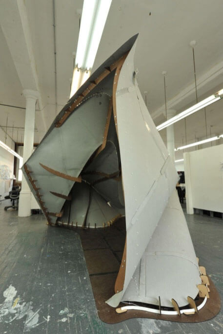
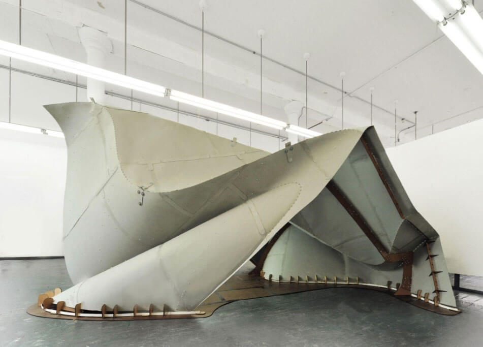
View of final project
Making a full-scale curved folding prototype
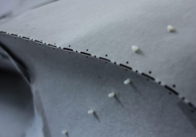
In order to create a rigorous case study, several constraints need to be established to ensure a direct correlation to the small-scale process of making models. The chosen material is vulcanized fiberboard, a paper that is treated with an acid such that the bonding properties between molecules increase. The result is a paper-like product that is much stronger. The paper is malleable while wet and can dry in a deformed state, which is useful when folding creases. Once the desired fold is achieved it can dry and stay in place. Using compliant hinges, which means folding the material without destroying it, has several advantages such as folding accuracy and force transfer within the surface. The constraint of creating the entire 2D assembly first means that the creases need to be folded while the material is wet and malleable. The flat 2D assembly requires careful coordination as sub-assemblies need to be CNC-cut and connected using specific sequences and joint details. The parametric model is set up such that it considers several conditions:
- panel-to-panel seams are adjusted when seams cross creases
- sub-assembly connections are reinforced by laminating patches
- bolt alignments and holes for stiffeners
The pulley system made of tripod cranes supports the assembly during construction as seen in the diagram below. Once the surface is in the correct position and dry, it can be set into the floor rails.
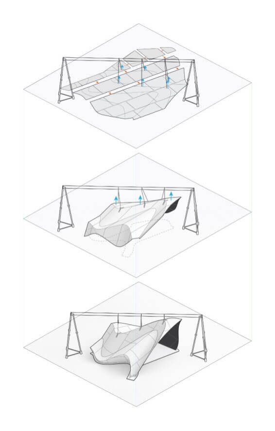
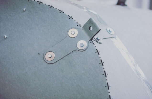
Assembly sequence from 2D to 3D with tripod cranes Details of compliant hinges and lifting tabs
Observations
The proposed methodology worked very well. The calibration of the small-scale investigations provided adequate feedback in terms of dynamic folding behavior, structural behavior, and aesthetics. The large-scale prototype provided feedback about the feasibility of this construction method. As the material is not a conventional building material it was necessary to develop specific tectonics for the flat assembly. While it is possible to build a shell using the proposed manner this project did not result in a true monocoque structure. The building of the full-scale shell provided several observations:
- The main forces are being taken on by the sheet itself, but thin ribs are needed in several locations.
- The lifting tabs did not deform the sheet as they were placed in the right locations.
- The panel-to-panel seams worked well for position control but did not perform well in tension.
This project served as a pilot for grant applications and has been published in two conferences, one focused on structural design and another on geometry. Two consecutive projects tackled the shortcomings of this project.
[student team of built prototype: Xuechen Chen (Research Assistant), Sharon Broyn, ChafiqEnnaoui, David Huh, Bharati Kodnani, Yen Chi Lee, Shaun Mehta, Jonathan Ovshayev, Massi Sur-ratt, Yuheng Wu, Runyu Zheng]
(b) RIBBON SURFACES FOR BENDING ACTIVE STRUCTURES
The research question for the next investigation is related to using meshes made of self-similar parts.
Which kind of 2D unit-based approach can be used for building an embedded bending active grid-shell? The 2D assembly units have structural, mechanical, and aesthetic properties which can be used for a self-supporting structure. Given the geometric and structural constraint of a bending active surface made of hexagonal cells, which type of shell can be designed and fabricated that uses 2” strap steel?
The geometry and design of bending-active surfaces
The use of elastically bent (bending-active) beam elements, as a support system integrated with membrane surfaces, offers a great potential for new shapes and highly efficient structural systems with pre-stressed membranes (Lienhard, J. et al. 2013). The nature of a bending active surface is that it finds its 3D configuration after forces have been introduced into it. In this case, the mesh surface consists of flat hexagonal units, which transform into a surface with negative curvature once two opposite points of the boundary are brought closer to each other. In the images below the mesh is bending between a thumb and a middle finger and automatically turns into a saddle-like surface.

2D to 3D transformation – the flat mesh automatically creates the shape on the right viainducing force
The specific topic of cell-based bending active surface grids was investigated by Riccardo La Magna in his thesis on bending-active plates (La Magna, R. 2017).Computer modeling and simulating of bending-active surfaces is relatively complex and it is possible to create an ‘analog’ – a physical scaled model – that behaves the same way as a full-scale structure. One can choose a material and then match the geometric constraints that drive the bending behavior. In this case, 3D printed PETG models turn out to be a productive method. The small-scale models have modified proportions relative to meshes made with strap steel and the edges of the units in the mesh are thicker than spring steel.
The design process is based on iterating through many versions of 3D-printed meshes. The physical models serve several purposes such as providing feedback on aesthetic qualities and on surface deformations under stress. The specific nature of bending active meshes is at first counterintuitive and manipulating physical models that behave similarly to the full-size mesh produces tacit knowledge. These physical models cannot replace simulation, but rather create a physical scaled artifact for learning and design purposes that is ‘good enough’.
The project
This grid shell is a free-standing structure made of 2” strap steel, which is generally used for industrial packaging. The mesh is a regular tiling or tessellation of hexagonal cells that are arranged as a parallelogram and an attached triangle as seen in the images below. The project was constructed as a flat assembly and subsequently lifted into place with pulleys and arrested in its final configuration with tension cables.
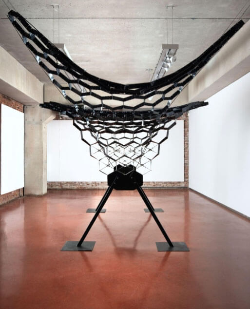

Front and oblique view of the final shell
Making a full-scale prototype
Regarding the material choice and technique of construction, the following requirements narrowed down available options. The material should be readily available, low-cost, non-toxic during fabrication, and fully recyclable. The main constraint relative to the construction process is based on making a 2D mesh on the floor and lifting it into a shape similar to Frei Otto’s Multihalle in Mannheim (Otto, F. 2018). The shell was erected with temporary scaffolding towers inside the grid shell to lift and subsequently tighten the wooden structure without any formwork.
The sequence of assembly demonstrates the 2D to 3D transformation well. The flat 2D assembly is connected with bolts on the floor. The mesh can then be hoisted into its final 3D shape and the last steps consist of installing tension cables and lifting the structure onto its legs as seen in the diagram below. The student team used ropes and pulleys on tripod poles to lift the surface at two ends before assembling the tension cables.
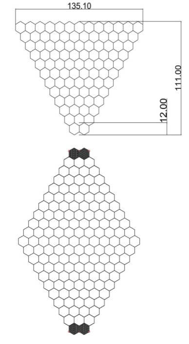

Diagrams of the flat 2D mesh and the assembly sequence: assemble mesh, hoist into place, attach triangle mesh
Strap steel is made of spring steel, which means its elastic and plastic deformations are different from regular steel. It is engineered for tension and is coated to resist corrosion during transport. Bending strap steel is relatively easy, drilling however poses challenges, which lead to several attempts including step drills and pneumatic punchers. The student team had to keep track of the positions of the rivet holes with jigs. The final bending method was using a brake press with jigs. The individual cells were assembled into patches with steel rivets, which is documented in the series of images below.
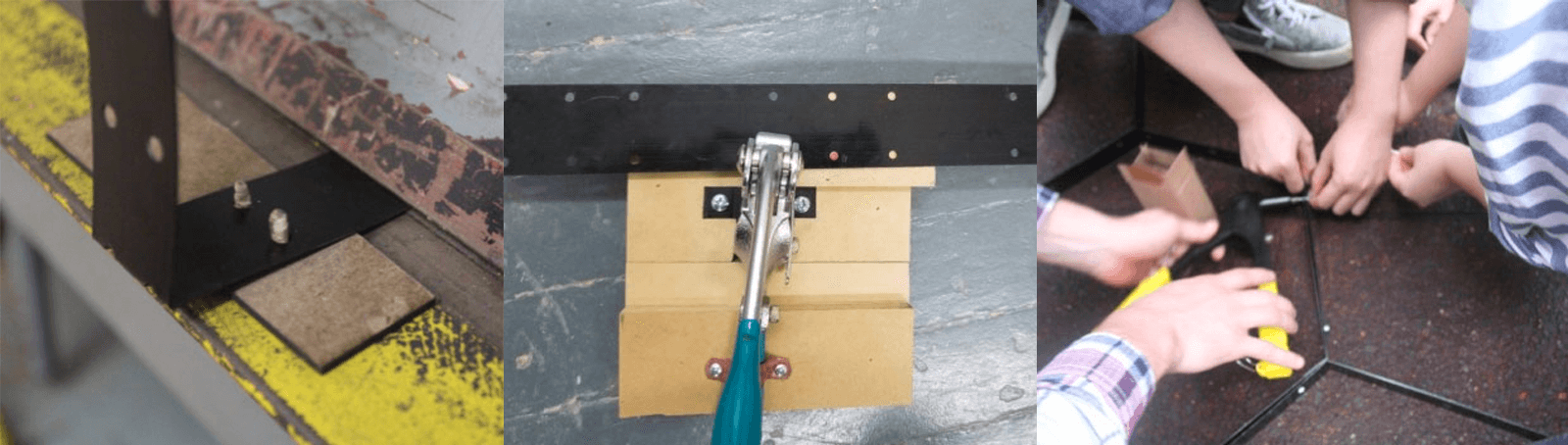
Bending strap steel on a brake press, position control for punching, mesh assembly
Observations
Following the proposed methodology proved to be productive for this investigation. The devised small-scale analog made of 3D printed PETG meshes worked very well. The upper boundaries of deformation as described in La Magan’s thesis were explored further to create thinner mesh surfaces. The mesh surface exceeded the upper bounds by a factor of two, which led to deformations due to gravity loads. The surface had to be reinforced with steel plates at the bottom where it is attached to the legs.
The final design was presented to a ‘Green Thumb’, which are community gardens managed by the Department of Parks. The members of the garden participated in reviews and gave students feedback on the programming. The project was subsequently exhibited during the ‘Research Open House’ at the Institute. The overall feedback was generally positive and led to a second iteration of the project that was investigating affordable alternatives to greenhouse construction. The proposed approach appears feasible for greenhouses but does not provide the necessary stiffness as an open structure.
[student team of built prototype: Irmak Ciftci (Research Assistant), Anabel Baquerizo, KhadeejaBoriyawala, Joshua Cooper, Jingfei Huang, Tyler Kruppa, Yalai Pang, Marie Park, Lindsay Unger, Shucong Wang, Xinyu Zhang, Xun Zhang]
(c) INFLATABLES WITH 2D TO 3D TRANSFORMATIONS
The last design research project in this series is an inflatable structure made in collaboration with Pneuhaus. The research question is related to the automatic 3D forming of flat assemblies that are welded together in 2D.
Given the method of welding together two planar patterned sheets of plastic, which 3D configurations can be achieved that are similar to a hyperbolic paraboloid?
2D to 3D transformation – the left planar welding pattern automatically creates the shape on the right when inflated
The geometry and design of stiff inflatable shells
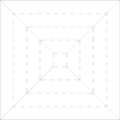
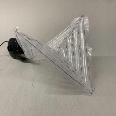
The origami pattern of concentric pleats resulting in a hyperbolic paraboloid shape, a hypar, translates from paperfolding into inflatable structures. The configuration made of concentric shapes forms into a hypar when inflated. The corollary between paperfolding and inflatables is not obvious, but recent work on this type of 2D to 3D transformation has shown how planar patterned sheets can be used to make stiff inflatable shells (Siéfert, E. et al. 2020). Students performed exhaustive studies in studios and seminars on how the shapes could be modified and organized to discover the maximal 3D deformation of the 2D welded pattern. Subtle changes in the planar pattern with concentric squares have different results in terms of wrinkling and 3D transformation as seen below.
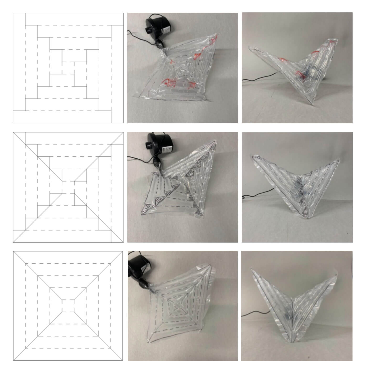
2D patterns and inflated hypar models
The project
The student work of a studio in 2021 was noticed by Ilene Shaw at NY Design Pavilion and she invited the d.r.a. Lab to create a new version of the project that could be used in a public setting in Times Square. The lab joined up with Pneuhaus to produce and exhibit the ‘Pop-up Drop-off’ Pavilion at NYCxDesign 2022. Working with plastic sheets and fabric raised the question of plastic pollution and recycling, which resulted in designing a structure that is entirely made of scrap pieces and fabric waste. The upper quilt is colorful and the lower quilt is made of various white leftover pieces in order to let the colors of the upper sheet register on the lower sheet. The design also addresses an optimized use of fabric as high-stress areas are made with heavier sheets. This kind of material optimization is often disregarded as the manufacturing time increases and projects become economically unfeasible. The purpose of this installation is to inform a general audience about film plastic recycling and its problems in NY State. The structure operates as a temporary drop-off location for plastic bags and other film plastic waste.
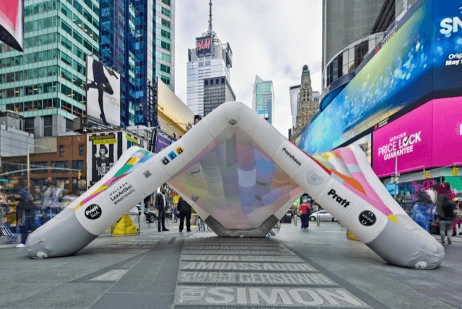
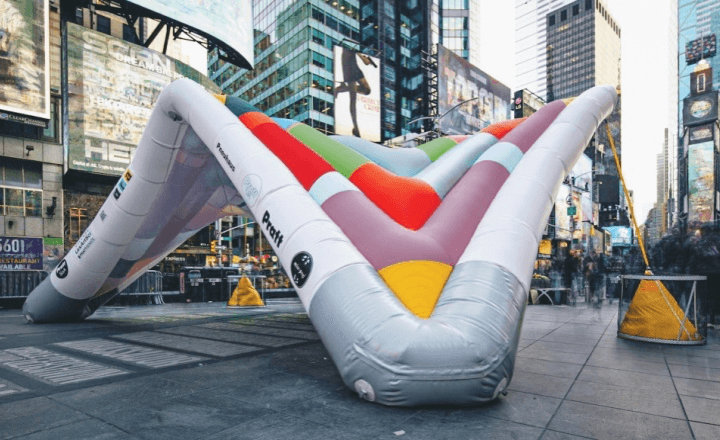
Frontal and oblique view of the final project on Times Square in New York City
Making a full-scale inflatable
The geometry of the project needed to accommodate NYC code requirements and the resulting form is less symmetrical in section than in earlier studies. The quilt was made of a large variety of scrap pieces of fabric that would normally have been discarded. Addressing the force transfer across the many additional seams required reinforcing for some of the structural seams. Several special anchors and custom point attachments had to be devised to allow for weights to be placed in 5 locations. The wind load requirements for Times Square are very high as this is a high-traffic area. The structure was engineered to withhold 70 m/h wind gusts.
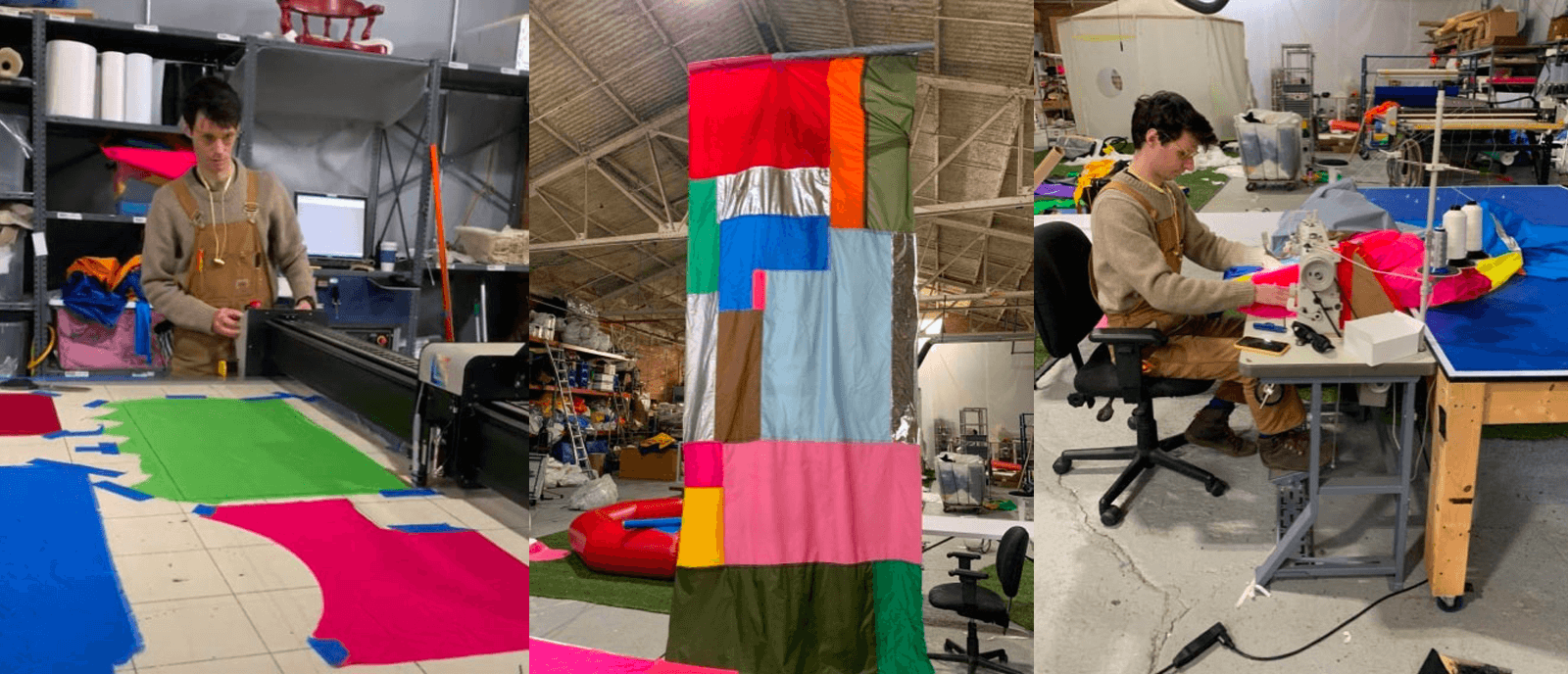
Making the quilt on a CNC cutter, an upper sheet with colorful cut-offs, sewing together the quilt into tubular chambers
Observations
Inflatables are often perceived as engaging and fun and can hence be used to communicate ideas to broad audiences. After several exhibitions of different projects, it became clear that this characteristic of inflated projects can be exploited to communicate ideas about sustainability with high impact. The project provides ample opportunities to engage the public in conversations about film plastic recycling.
The scaling and windproofing of the project demanded altered details for footings and cantilevered areas compared to early studies. The geometry of the project is based on the hypar studies but was not made with a planar pattern. The next iteration of this project will be made with large sheets of recycled sheets in order to compare the structural feasibility of planar pattern assemblies.
Hannah Bacsoka (Research Assistant)
CONCLUSION
We have developed a way of working that allows us to conduct rigorous design research. A small-scale ‘analog’ – if well defined – can perform in similar ways to full-scale prototypes just like form-finding models worked for hanging shapes since Antoni Gaudí. We have expanded this method with other form-active structures and are aspiring to discover more examples. The full-scale prototype serves as a proof-of-concept that allows for a different way to evaluate the work such as testing structural systems and assembly methods and determining if they are feasible for future development.
The above case studies elucidate how to structure design research using a specific methodology. The agenda consists of defining a study in rigorous terms and to arrive at a design solution that can be evaluated by broader audiences. The proposed steps of the methodology which include a form-finding method, creating an ‘analog’ for experimentation, and finally making full-scale prototypes have shown to work well for this type of design research.
The resulting projects and their documentation contribute to knowledge production in several ways. If details and assembly methods are truly novel ideas, one can think of the work as innovation in engineering. Alternatively, if the work confirms current engineering knowledge, but results in novel design solutions, one can think of the work as a contribution to building technology. However, in either case, design plays an important role and aesthetic contributions are made along the way.
Design knowledge can be produced at several levels, as a geometry study that is tied to a specific material process or as a designed project in a public context. Design can thereby become part of architectural discourse and gain agency at the public level.
Acknowledgments
The cited work above was conducted in the d.r.a. Lab (design research in architecture), which aspires to advance knowledge that correlates topics in geometry to the fabrication of assemblies in order to provide sustainable building solutions. The lab is situated in the School of Architecture at Pratt in Brooklyn, NY focusing on interdisciplinary design research that combines topics in geometry, digital fabrication, and material science.